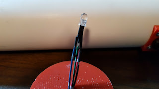
LEDs were gathered to start wiring the first tagger. Laser modules hadn't arrived so green LEDs would take their place until then, red LEDs would be the report emulator for simulating muzzle flash, white (clear) LEDs would act as a flashlight, RGB LEDs tell the player the game status, infrared (IR) LEDs transmit data to opponents, and the IR receivers (three leads) receive data from opponents.
Green — temporary stand-in for laser
Red — report simulator
White — flashlight
RGB — player/game status
IR emitter — data transmission
IR receiver — data reception
Component leads right next to one another had to be insulated to keep them from shorting. Heat-shrink tubing was placed around each lead, including the ground. Insulating the ground wasn't necessary since the rest of the components were covered but it seemed logical to protect it anyway.
Every component in the first tagger which wasn't in the forward array, was given wires. This was the reload button, trigger switch, and RGB LED. The IR components were not wired yet.
The end of the wires connecting to the computer were given DuPont ends so they could be rearranged on the pins as desired. Connecting this way gave a modestly reliable connection but made it as easy to change locations as a breadboard.
Downloads:
The rest of the posts for this project have been arranged by date.
First time here?
Completed projects from year 1.
Completed projects from year 2.
Completed projects from year 3.
This blog, including pictures and text, is copyright to Brian McEvoy.
Green — temporary stand-in for laser
Red — report simulator
White — flashlight
RGB — player/game status
IR emitter — data transmission
IR receiver — data reception
Light emitting devices
Component leads right next to one another had to be insulated to keep them from shorting. Heat-shrink tubing was placed around each lead, including the ground. Insulating the ground wasn't necessary since the rest of the components were covered but it seemed logical to protect it anyway.
Every component in the first tagger which wasn't in the forward array, was given wires. This was the reload button, trigger switch, and RGB LED. The IR components were not wired yet.
The end of the wires connecting to the computer were given DuPont ends so they could be rearranged on the pins as desired. Connecting this way gave a modestly reliable connection but made it as easy to change locations as a breadboard.
RGB LED: Wired
RGB LED Pi ends
Reload button: wired
Trigger switch: wired
Downloads:
The rest of the posts for this project have been arranged by date.
First time here?
Completed projects from year 1.
Completed projects from year 2.
Completed projects from year 3.
Disclaimer for http://24hourengineer.blogspot.com/
This disclaimer must be intact and whole. This disclaimer must be included if a project is distributed.
All information in this blog, or linked by this blog, are not to be taken as advice or solicitation. Anyone attempting to replicate, in whole or in part, is responsible for the outcome and procedure. Any loss of functionality, money, property or similar, is the responsibility of those involved in the replication.
All digital communication regarding the email address 24hourengineer@gmail.com becomes the intellectual property of Brian McEvoy. Any information contained within these messages may be distributed or retained at the discretion of Brian McEvoy. Any email sent to this address, or any email account owned by Brian McEvoy, cannot be used to claim property or assets.
Comments to the blog may be utilized or erased at the discretion of the owner. No one posting may claim property or assets based on a post.
2017-03-09 (Th)


Comments
Post a Comment