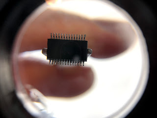
When testing IO, any missing connection probably meant that a pin on the IC was not soldered correctly. Sadly, this was not always an easy fix. A fine-tip soldering iron can fix the problem by adhering a loose pin, but that is not always the problem. In one case, a new IC had to replace a scorched IC on the back of a 4x4 board. When the new chip was installed, there was a solder bridge between two of the pins.
A soldering iron was used to try to wipe away the solder bridge, but it was ineffective. A piece of wire was heated with the hope that the solder would prefer the copper wire and enough would plate the wire and leave the chip. Of course, none of these worked so the chip was entirely removed and the glob of solder was shaken off with the chip removed.
With all offending solder removed, the chip socket was reheated with a hot air station, and the IC was soldered back in place. This method, while a bit time-consuming, worked very well and the computer was able to see the device and read all the IO properly.
The breakout board was showing problems, which may have had to do with a broken wire. Testing for continuing was difficult so a scrap of wire was bent into a shape which could be easily replaced and removed. In the animation below, it can be seen triggering the red lights which indicated that it was making a connection.
All the IO tested well after fixes were made, so keyswitches were installed on the entire left half of the keyboard. The next step will be testing IO on the right side of the keyboard and installing those keyswitches.
ModuKey on GitHub
The rest of the posts for this project have been arranged by date.
First time here?
Completed projects from year 1
Completed projects from year 2
Completed projects from year 3
Completed projects from year 4
Completed projects from year 5
Disclaimer for http://24hourengineer.blogspot.com/
This disclaimer must be intact and whole. This disclaimer must be included if a project is distributed.
All information on this blog, or linked by this blog, is not to be taken as advice or solicitation. Anyone attempting to replicate, in whole or in part, is responsible for the outcome and procedure. Any loss of functionality, money, property or similar, is the responsibility of those involved in the replication.
All digital communication regarding the email address 24hourengineer@gmail.com becomes the intellectual property of Brian McEvoy. Any information contained within these messages may be distributed or retained at the discretion of Brian McEvoy. Any email sent to this address, or any email account owned by Brian McEvoy, cannot be used to claim property or assets.
Comments to the blog may be utilized or erased at the discretion of the owner. No one posting may claim property or assets based on their post.
This blog, including pictures and text, is copyright to Brian McEvoy.
2018-11-11
Solder bridge on SMD component
A soldering iron was used to try to wipe away the solder bridge, but it was ineffective. A piece of wire was heated with the hope that the solder would prefer the copper wire and enough would plate the wire and leave the chip. Of course, none of these worked so the chip was entirely removed and the glob of solder was shaken off with the chip removed.
Solder cleared when the chip was removed
With all offending solder removed, the chip socket was reheated with a hot air station, and the IC was soldered back in place. This method, while a bit time-consuming, worked very well and the computer was able to see the device and read all the IO properly.
Reinstalled chip
The breakout board was showing problems, which may have had to do with a broken wire. Testing for continuing was difficult so a scrap of wire was bent into a shape which could be easily replaced and removed. In the animation below, it can be seen triggering the red lights which indicated that it was making a connection.
Testing input with wire jumper
All the IO tested well after fixes were made, so keyswitches were installed on the entire left half of the keyboard. The next step will be testing IO on the right side of the keyboard and installing those keyswitches.
Populating boards with keyswitches
ModuKey on GitHub
The rest of the posts for this project have been arranged by date.
First time here?
Completed projects from year 1
Completed projects from year 2
Completed projects from year 3
Completed projects from year 4
Completed projects from year 5
Disclaimer for http://24hourengineer.blogspot.com/
This disclaimer must be intact and whole. This disclaimer must be included if a project is distributed.
All information on this blog, or linked by this blog, is not to be taken as advice or solicitation. Anyone attempting to replicate, in whole or in part, is responsible for the outcome and procedure. Any loss of functionality, money, property or similar, is the responsibility of those involved in the replication.
All digital communication regarding the email address 24hourengineer@gmail.com becomes the intellectual property of Brian McEvoy. Any information contained within these messages may be distributed or retained at the discretion of Brian McEvoy. Any email sent to this address, or any email account owned by Brian McEvoy, cannot be used to claim property or assets.
Comments to the blog may be utilized or erased at the discretion of the owner. No one posting may claim property or assets based on their post.
This blog, including pictures and text, is copyright to Brian McEvoy.
2018-11-11


Comments
Post a Comment